


One of the biggest determinators to the successful creation of a machined part is in your fixturing. The basic goal when fixturing a part is to keep that part in place and not allow it to move while it is being machined. If the part moves whatsoever, there is a good chance you’ve just made a scrap part.
The Mentality
The basic premise of achieving a properly fixtured part is to isolate and lock it in all degrees of freedom. There are a total of 6 degrees of freedom. A degree of freedom is essentially an axis about which the part can move. There are rotation axis’ as well as linear axis’ as shown below.
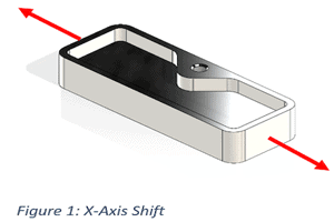
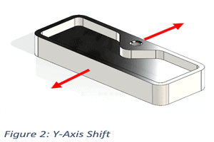
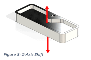
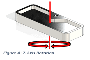
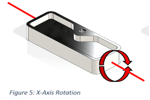
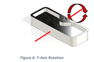
If we secure these axis’ from movement as shown above, we have successfully fixtured the part. Keeping in mind, we also have to ensure that everything is held securely as there are some cutting forces that occur when being machined. Next we will talk about some of the methods for locking these axis’.
The Methodology
Firstly, we will talk about the various types of devices you can utilize for fixturing.
Locators
Locators are heavily used when designing fixturing. There are several different types of locators and it would be impossible to go over every single type but the most common are round, diamond, dowels, cones, and bullet-nose locators.
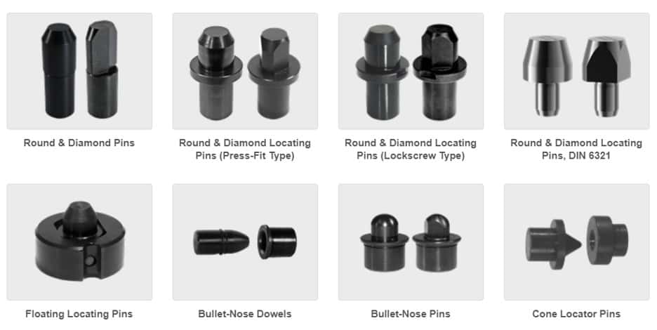
Photo courtesy of Carr-Lane
Bore Clamps
Bore clamps can be used to hold onto inner diameters of a part and they expand using a set screw to apply force evenly on the bore. These types of clamps will automatically center the bore onto the clamp. Below is a cross sectional view of these clamps so you can understand how they work.
You can see that the screw is tapered inside as well as the slotted clamp body. As you tighten down the screw, it exerts force outward and spreads the slotted segments apart which increase its diameter to interfere with the bore of the part being located. A simple yet highly effective design.
Buttons/Rests
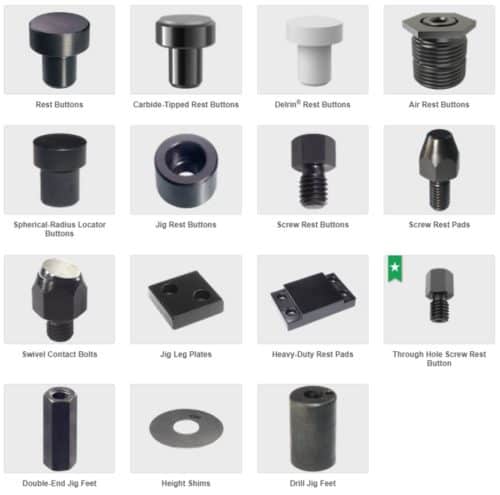
Photo courtesy of Carr-Lane
Another common fixturing component are buttons or rests. These are simply a generally hardened platform or insert that mates up against a face or contact point on the part to locate it. It could act as a support for clamping the part against as well. Some common benefits are if these components wear, you can easily pop them out of the fixture and replace them with a new one.
Dovetails
Dovetails are one of the most versatile fixturing methods. The reason or this is due to the number of axis’ it locks simultaneously. The use of dovetails with a vice will successfully lock all of the 6 axis’ of freedom as seen below.
As you can see, when the vice is clamped and both dovetails are engaged, the part will be unable to move in any of the 3 axis of linear movement. It also cannot rotate in any direction either. This is the power of dovetails. However, you will typically add an extra machining operation to remove the excess material you would have left around the part to allow you to machine the dovetail into the part.
Fluid Power
Many fixtures especially for high production; take advantage of fluid power (hydraulic or pneumatically actuated devices) in order to quickly and automatically engage the part into the fixture. These can range from a simple hydraulic cylinder to clamp a part down; all the way to highly complex sequencing valves which locate and clamp the part in a sequence. This can greatly increase repeatability and speed of loading the part.
Application of Concepts
Now that we have gone over the basics of fixturing, let’s fixture the part we looked at earlier.

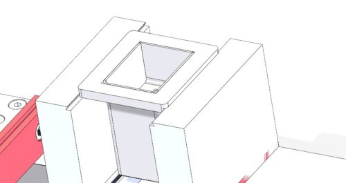
It is incredibly important when fixturing to ensure you abide by the intended datums on the drawing. For the purpose of this demonstration, we have labelled the part above’s datums so we can fixture it. For a further explanation of datums and GD&T, see our other content here. (implied link in future) You will notice that the datums themselves lock the part in 3D space, the converging single point of datum A (the left side edge), datum B (the top plane of the top face), and datum C (the backside edge) all converge together to a single point which is our top left corner (indicated by the blue dot). When our datum is a corner, this tells us we need to precisely locate that corner and then clamp it down to the table to lock all of our axis’.
The goal of this operation is to add 4 holes to the bottom of the previously machined pocket in order to make the part look like this:
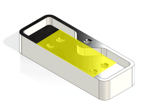
We need to make sure that our fixturing does not get in the way of the CNC machining spindle or the tapping arm that will be coming in to drill and tap these holes. Therefore, we cannot put anything in the yellow highlighted region shown above.
We are going to go over 2 ways to fixture this. The first method will be using some of the previously modular fixturing devices and the second method will be using a vice and offset. Both of these methods have their place and it depends on the situation which you would utilize.
Method 1 – Modular Fixturing
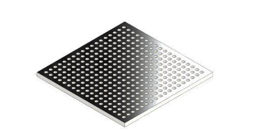
In modular fixturing you typically have a modular tooling plate with a bunch of precision-machined holes which can fit these modular devices like the one shown.
Let’s put a couple of locators on the plate and place the corner of our part up against them to restrict some axis’.
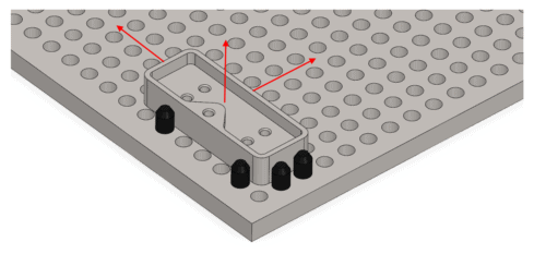
Now we can see the remaining axis, which are still not controlled, by our locators. We have locked rotation in all axis however we still have 3 directions our part can move in (red arrows). We need something that will push our part securely up against the pins in both directions and then another method to clamp the part firmly downwards. We can achieve this with 3 clamps.
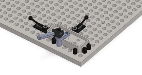
With the addition of two edge clamps and one hold down clamp we have successfully fixtured our part and locked all axis of movement.
Method 2 – Vice & CNC Machine Offset
In practice, many simple parts can be fixtured with something as simple as some parallel bars and a vice. Let’s look at how this works. First let’s add the parallel bars. These bars ensure that the part we put into the vice has an even and flat surface to rest up against while also allowing us to raise the part up high enough to access the part.
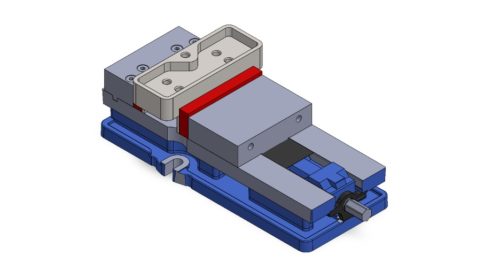
As you can see, we have effectively locked all the axis’ of this part which is fantastic. However, we have not located the left-hand side of this part. Our CNC machine needs to know where this part is. On the past modular method, you would take a machining offset on the modular plate because you know that the part will orient in the same place every time. However, with this method you will be required to take an offset off each part which is not always ideal especially when doing multiples of the same part. A machining offset is a point in space that the operator programs into the CNC machine in order for it to know where the program begins in 3D space. It has to know where the part is to know where to machine.
For more information about our services or to request a quote, contact us today!